Permanent and alternating current with your own hands will not take much time and effort.
The main condition for its creation is a clear idea of what kind of welding work it should perform and instructions.
To carry out welding, you need a device that runs on AC and direct current.
Thin metal sheets are welded using a current machine. This welding method does not require the use of a specific type of electrode, and the electrode wire can be without ceramic coating.
The welding machine circuit consists of 5 parts. The current circuit passes through the welding machine, first entering the transformer.
From there, the current flows into a rectifier, whose diodes convert alternating current to direct current, and a choke. The last elements of current flow are the holder and the electrode.
The electrode holder is connected to the rectifier using a throttle. This smoothes out the tension pulse.
A choke is a coil of copper wires wound around a core. And the rectifier is a part of the device connected to the transformer through the secondary winding.
A transformer is connected to the network - the main part of the device. You can either purchase it specially or use a previously used but usable transformer.
It converts AC voltage according to Ohm's law.

So the voltage generated on the secondary winding decreases, but at the same time the current increases 10 times. Welding occurs at a current of 40 amperes.
The electrical circuit is closed the moment an arc appears between the electrode and the pieces of metal being welded.
The arc must burn stably, then the weld will be made with high quality. An electrical power regulator will help in establishing the desired combustion pattern.
The most basic diagram of the unit
It is better if the electrical circuit of the unit is very basic.
An easy-to-assemble device, assembled with your own hands, must be connected to a network with an alternating current voltage of 220 Volts.
A voltage of 380 Volts requires a more complex welding machine design.
The most simple circuit- this is a circuit for a pulsed welding method, which was invented by radio amateurs. This welding is used to attach wires to a metal board.
To build this device with your own hands, you don’t need to do anything complicated, you only need a couple of wires and a choke. The choke can be removed from the fluorescent lamp.
The current regulator can easily be replaced with a fuse-link. It is better to stock up on large quantities of wires.
To connect the electrode to the board, take a choke. An alligator clip can serve as an electrode. The finished unit must be connected to the network by inserting a plug into the socket.

Using the clamp connected to the wire, you need to quickly touch the area to be welded on the board.
This is how a welding arc appears. During its occurrence, there is a danger that the fuses located in the electrical panel will burn out.
The fuses are protected from this danger by a fuse link that burns faster.
As a result, the wire remains welded to its place.
Such a direct current device is the simplest welding machine. It is connected to the electrode holder by wires.
But it seems possible to work with it only at home, since this scheme It is devoid of important parts - a rectifier and a current regulator.
Equipment for welding unit
Compared to traditional devices, a three-phase unit inverter type compact, easy to use, reliable. There is only one nuance that makes you think about it during the purchase - the rather high price.
Even superficial calculations suggest that making a welding machine with your own hands will be cheaper.
If you approach the selection of the necessary elements with all seriousness, then a homemade welding tool will last a long period of time.
In general, the welding machine circuit consists of three blocks: a rectifier block, a power supply and an inverter block.
A homemade AC and DC apparatus can be equipped so that it can be light in weight and have a small size.
A homemade welding machine can be easily built with your own hands, using objects available to everyone.
All the parts needed to create a welding unit are available in electrical equipment or in devices where some elements have failed.
You can build a simple current regulator from part of the heating coil used in an electric stove.
If you couldn’t find any necessary parts at all, then it’s okay - you can make them yourself.
Piece copper wire can serve as a material for creating such an important element of a DC and AC welding unit as a choke.
Specifically for its assembly you will need a magnetic circuit, which has an old starter. You also need 2-3 copper wires with a cross-section of 0.9 - and you can get a choke.
The transformer for the welding unit can be an autotransformer or the same part removed from an old microwave oven.
When removing the necessary element from it, you need to be careful not to damage the primary winding.
And the secondary one will have to be redone anyway; the number of new turns depends on the power of the unit being designed.
The rectifier is assembled on a board made of either getinax or textolite.
The diodes for the rectifier must correspond to the selected power of the unit. To keep them cool, an aluminum alloy radiator is used.
Sequential assembly of all parts
All elements of the welding unit must be located on a base made of metal or textolite strictly in their places.
According to the rules, the rectifier is adjacent to the transformer, and the inductor is located on the same board with the rectifier.
The current regulator is installed on the control panel. The frame itself for the structure of the unit is created from aluminum sheets; steel is also suitable for this.
You can also use a ready-made case, which previously protected the contents of the system unit of a computer or oscilloscope. The main thing is that it must be strong and solid.
A board with thyristors is placed at a great distance from the transformer. The rectifier is also not installed close to the transformer.
The reason for this arrangement is the strong heating of the transformer and inductor.
Thyristors mounted on aluminum radiators remove heat from the inductor. They even cancel out the heat waves emanating from the wires.
An electrode holder is attached to the outer panel, and a wire with a plug is attached to the rear panel to connect the unit to a household network.
The video in our article demonstrates how to assemble a welding unit with your own hands.
Under no circumstances should the elements of the unit be fixed close to each other, as they must be subject to airflow.
It is necessary to make holes on the sides of the frame from where air will flow. This is also necessary for installing a cooling system.
If the welding unit is constantly in the same place, then it is unlikely that anything will happen to it.
The current regulator, or more precisely, its handle fixed on the outer wall, will be able to work for a long time.
But portable mini-inverters that are taken for field work may be subject to mechanical shocks. Basically, the body of the product suffers from this, but there is a risk of the throttle falling off.
The product is assembled - it’s time to check how it functions. When testing the operation of the welding unit, temporary wires must not be used.
You need to check the product with standard contact cables.
During the very first connection to the network, look at the current regulator. It is important to ensure that there are no unfixed parts left.
If the unit is in good working order and free from defects, then you can start welding in various modes.
Direct current welding (TIG DC)- this is one of the types argon arc welding, which is used for high-quality joining of most metals that do not form a refractory oxide film on the surface of the product during the melting process.
Principle of operation machines for welding with direct current (TIG DC) is based on pulse width modulation or PWM. The inverter circuit is presented powerful transistors, which rectify the mains voltage and convert it into alternating high-frequency voltage up to 100 KHz. Next, the voltage is supplied to the primary winding of the transformer, and from the secondary winding the high-frequency alternating voltage is converted to direct voltage.
TIG welding machines can perform welding with both “straight” and “reverse” polarity. “Straight” polarity is used for high-quality welding of titanium, high-alloy steel and other metals. With “straight” polarity, minimal heating of the electrode and maximum penetration of the metal being processed occurs. With “reverse” polarity, TIG machines allow using cathode sputtering to remove the oxide film (Al2O3), which is formed during the welding process of aluminum and other refractory metals. However, in this case, due to the strong heating of the electrode, the tungsten electrode quickly burns out.
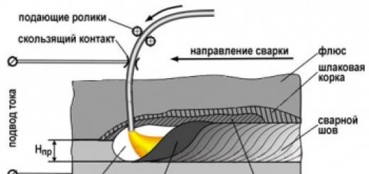
When using TIG DC machines, the arc is excited between the metal and the tungsten electrode, to which the welding current is supplied. In this case, through special nozzles in the TIG torch, a protective gas (argon) is supplied to the welding zone, which creates a shell and eliminates the influence of the atmosphere on the formation of the seam.
Modern welding equipment of the TIG DC series is used for processing products made of high-alloy and stainless steels, carbon and medium-alloy steels, titanium and copper, zinc, alloys based on them and other metals.
Universal TIG DC machines used for repair and production work, in the construction industry, in the manufacture of ventilation and heating systems, in the chemical and food industries, in machine tool industry, in the production of pipelines, etc.
Advantages of TIG DC welding:
- high quality welding connection;
- no metal spattering;
- the ability to perform welding in any spatial position;
- absence of slag formations;
- virtually no seam modification is required;
- excellent visual control of the welding arc and seam formation.
- Welding experience required;
- the difficulty of welding outdoors in strong winds or drafts;
- use of a gas cylinder with argon;
- low productivity.

20 years ago, at the request of a friend, I built him a reliable welder to work on a 220-volt network. Before this, he had problems with his neighbors due to a voltage drop: an economical mode with current regulation was required.
After studying the topic in reference books and discussing the issue with colleagues, I prepared electrical diagram control on thyristors, mounted it.
In this article, based on personal experience, I tell you how I assembled and configured a DC welding machine with my own hands based on a homemade toroidal transformer. It came out in the form of a small instruction.
I still have the diagram and working sketches, but I can’t provide photographs: there were no digital devices then, and my friend moved.
Versatile capabilities and tasks performed
A friend needed a machine for welding and cutting pipes, angles, sheets of different thicknesses with the ability to work with 3÷5 mm electrodes. ABOUT welding inverters They didn’t know at the time.
We settled on the DC design, as it is more universal and provides high-quality seams.
Thyristors removed the negative half-wave, creating a pulsating current, but did not smooth out the peaks to an ideal state.

The welding output current control circuit allows you to adjust its value from small values for welding up to 160-200 amperes required when cutting with electrodes. She:
- made on a board from thick getinax;
- covered with a dielectric casing;
- mounted on the housing with the output of the adjusting potentiometer handle.
The weight and dimensions of the welding machine were smaller compared to the factory model. We placed it on a small cart with wheels. To change jobs, one person rolled it freely without much effort.
The power cord was connected through an extension cord to the connector of the input electrical panel, and the welding hoses were simply wound around the body.
Simple design of DC welding machine
Based on the installation principle, the following parts can be distinguished:
- homemade transformer for welding;
- its power supply circuit is from network 220;
- output welding hoses;
- power block thyristor regulator current with electronic circuit control from a pulse winding.

Pulse winding III is located in power zone II and is connected through capacitor C. The amplitude and duration of the pulses depend on the ratio of the number of turns in the capacitor.
How to make the most convenient transformer for welding: practical tips
Theoretically, you can use any model of transformer to power the welding machine. The main requirements for it:
- provide arc ignition voltage at idle speed;
- reliably withstand the load current during welding without overheating the insulation from prolonged operation;
- meet electrical safety requirements.
In practice, I have come across different designs of homemade or factory-made transformers. However, they all require electrical engineering calculations.
I have been using a simplified technique for a long time, which allows me to create fairly reliable transformer designs of medium accuracy class. This is quite enough for household purposes and power supplies for amateur radio devices.
It is described on my website in the article This is an average technology. It does not require clarification of the grades and characteristics of electrical steel. We usually don’t know them and cannot take them into account.
Features of core manufacturing
Craftsmen make magnetic wires from electrical steel of various profiles: rectangular, toroidal, double rectangular. They even wind coils of wire around the stators of burnt-out powerful asynchronous electric motors.
We had the opportunity to use decommissioned high-voltage equipment with dismantled current and voltage transformers. They took strips of electrical steel from them and made two donut rings out of them. The cross-sectional area of each was calculated to be 47.3 cm 2 .
They were insulated with varnished cloth and secured with cotton tape, forming a figure of a reclining figure eight.

They began to wind the wire on top of the reinforced insulating layer.
Secrets of the power winding device
The wire for any circuit must have good, durable insulation, designed to withstand long-term operation when heated. Otherwise, it will simply burn during welding. We proceeded from what was at hand.
We received a wire with varnish insulation, covered with a fabric sheath on top. Its diameter - 1.71 mm is small, but the metal is copper.
Since there was simply no other wire, they began to make the power winding out of it with two parallel lines: W1 and W’1 with the same number of turns - 210.
The core donuts were mounted tightly: this way they have smaller dimensions and weight. However, the flow area for the winding wire is also limited. Installation is difficult. Therefore, each power half-winding was separated into its own magnetic circuit rings.
In this way we:
- doubled the cross-section of the power winding wire;
- saved space inside the donuts to accommodate the power winding.
Wire alignment
You can get a tight winding only from a well-aligned core. When we removed the wire from the old transformer, it turned out to be bent.
We figured out the required length in our minds. Of course it wasn't enough. Each winding had to be made from two parts and spliced with a screw clamp directly on the donut.
The wire was stretched along its entire length on the street. We picked up the pliers. They clamped the opposite ends and pulled with force in different directions. The vein turned out to be well aligned. They twisted it into a ring with a diameter of about a meter.
Technology of winding wire on a torus
For the power winding, we used the rim or wheel winding method, when a ring is made from the wire large diameter and is wound inside the torus by rotating one turn at a time.
The same principle is used when putting a winding ring on, for example, a key or keychain. After the wheel is inserted inside the donut, they begin to gradually unwind it, laying and fixing the wire.
This process was well demonstrated by Alexey Molodetsky in his video “Winding a torus on a rim.”
This work is difficult, painstaking, and requires perseverance and attention. The wire must be laid tightly, counted, the process of filling the internal cavity must be monitored, and the number of turns wound must be recorded.
How to wind a power winding
We found it for her copper wire suitable section - 21 mm 2. We estimated the length. It affects the number of turns, and the no-load voltage necessary for good ignition of the electric arc depends on them.
We made 48 turns with the middle terminal. In total, there were three ends on the donut:
- middle - for direct connection of the “plus” to the welding electrode;
- the extreme ones - to the thyristors and after them to ground.
Since the donuts are fastened together and the power windings are already mounted on them along the edges of the rings, the winding of the power circuit was carried out using the “shuttle” method. The aligned wire was folded like a snake and pushed through the holes of the donuts for each turn.
The middle point was unsoldered using a screw connection and insulated with varnished cloth.
Reliable welding current control circuit
The work involves three blocks:
- stabilized voltage;
- formation of high-frequency pulses;
- separation of pulses into circuits of thyristor control electrodes.
Voltage stabilization
An additional transformer with an output voltage of about 30 V is connected from the power winding of the 220 volt transformer. It is rectified by a diode bridge based on D226D and stabilized by two zener diodes D814V.
In principle, any power supply with similar electrical characteristics of current and output voltage can work here.

Pulse block
The stabilized voltage is smoothed by capacitor C1 and supplied to pulse transformer in two bipolar transistor direct and reverse polarity KT315 and KT203A.


Transistors generate pulses to the primary winding Tr2. This is a toroidal type pulse transformer. It is made of permalloy, although a ferrite ring can also be used.
Winding of three windings was carried out simultaneously with three pieces of wire with a diameter of 0.2 mm. Made 50 turns. The polarity of their inclusion matters. It is shown by dots in the diagram. The voltage on each output circuit is about 4 volts.
Windings II and III are included in the control circuit for power thyristors VS1, VS2. Their current is limited by resistors R7 and R8, and part of the harmonic is cut off by diodes VD7, VD8. Appearance We checked the pulses with an oscilloscope.
In this chain, resistors must be selected for voltage pulse generator so that its current reliably controls the operation of each thyristor.
The unlocking current is 200 mA, and the unlocking voltage is 3.5 volts.

Welding is a simple and reliable way to connect permanent metal. Welding work is carried out using special equipment, ranging from microelectronics to heavy construction.
Today, welding is carried out using direct and alternating voltage. In AC welding installations, the main element is a transformer of any structure. And in welding devices with constant flow energy they use power rectifier blocks. Correctly selected electric welding electrodes are the key to quality work.
What is alternating current in welding
Alternating voltage gets its name because the flow of electrons continuously changes the direction of its movement. During a welding process that consumes alternating current, the arc continuously "jumping". This happens due to regular deviation from the axis of the welding arc. Of course, this affects the quality of the resulting seam. As a result, the scar is wide, and metal droplets form at the junction. If the arc goes out, the ignition can be restarted by increasing the voltage.

With all this, equipment for alternating electric welding has its advantages:
- Simple design.
- Great working resource.
- The strength of the welding current can be adjusted.
Transformers continue to enjoy their popularity.
DC Welding
Welding machines permanently support 2 operating modes - the process of connecting with direct and reverse polarity. When using such installations, it is necessary to regularly monitor their operating mode, since some metals are seized in direct polarity, while others are seized in reverse polarity.

Most widely used straight polarity. The welded crater is deep and narrow. The heat supply decreases, the passage speed increases. It is used for cutting metal, has a stable arc, resulting in a high-quality connection. Used when working with steel, thickness from 4 mm. Most materials are welded using straight polarity.
Reverse polarity is used to join thin metals of medium thickness. The electric welding seam is not deep, but wide enough. With this polarity, you cannot use electrodes that are sensitive to overheating.
The main advantages of constant voltage welding are:
- No splashes of molten metal.
- Electric arc stability.
Differences between DC and AC electrodes
Electrodes conditionally do not differ. But constant power flow is not suitable for AC connection. Electric welding materials that are designed for alternating periods are also successfully used for electric welding using direct electricity. Experts call the resulting electrodes universal.
Universal electrodes are characterized by:
- A good and stable arc that even re-ignites easily.
- Volumetric production of work.
- High profitability.
- Low degree of splashing.
- Good separation of impurities.
- The ability to safely weld contaminated, oxidized, rusty and wet materials.
- The simplest requirements for the device and the employee.
A feature of universal electric welding electrodes is the ability to make a connection of metal products, even if there is large distance between metal parts. They are excellent for electric welding short seams and spot tack welding.
Comparing welding on constant and AC voltage, devices with a constant flow of energy have more advantages. Welding materials are saved, since spattering is minimal. The constant is simple and easy to use and is used for thin-walled products. Exposure to weather conditions does not affect arc stability, ensuring high performance. All areas of the structure are boiled, as a result the specialist receives a high-quality and neat scar.
The variable device provides good quality connections, simplicity and convenience of the welding process. Equipment that operates on this type of voltage is much cheaper.
The main difference between alternating and direct electricity is that the electrode is supplied with current or alternating frequency during operation. 50 Hz or constant. The design of a constant flow welding machine has rectifiers in the form of diodes, which rectify the electricity at the output and create a constant-sign pulsating value. Modern semiconductor rectifiers guarantee high performance and high efficiency. Consequently, better welding will be achieved using a constant flow. As practice has shown, alternating electrodes are a thing of the past.

Welding current is the most important parameter on which a quality connection depends. The diameter of the electrode must be selected taking into account the thickness of the metal. And based on its diameter, electricity is set. This information can be found on the packaging. There are no exact and specific voltage settings - each master is guided by his own feelings and sets the desired voltage parameter.
Special stores have a very wide selection of electrodes for arc welding. When purchasing, pay attention to the quality of the product and the presence of a license.
A welding machine is one of the most popular equipment in the world. Welding work is carried out everywhere and on a very large scale.
Of course, there are many varieties of these devices, differing in operating principles, dimensions, output amperage, and others. technical specifications And. There is also equipment that operates on alternating and direct current.
The DC welding machine is the most common because... supports 2 operating modes - welding of direct (minus on the electrode, and plus on the part) and reverse (vice versa, plus on the electrode, minus on the part) polarity. Very often it is necessary to change operating modes, because... Some metals adhere well in direct polarity, while others in reverse polarity.
The choice of one or another device is closely related to what goals the welder himself adheres to:
- What metal will be welded (type and thickness);
- What current (its voltage and strength) is present at the work site;
- How long will the welding machine have to work without rest?
- And other situations.
Welding machines used in industry, production, construction, etc. different from those used at home. The main difference between them is power and, accordingly, cost.
Today, so-called inverters - electric arc welding machines - are very successful on the market. They are excellent for carrying out almost any welding work, of any complexity and volume. They are also most often used in everyday life for two simple reasons - they are small in size and low in cost. In addition, inverters are easy to use and easy to repair. And an electronics engineer, even with a basic set of knowledge, is able to create a homemade DC welding machine from numerous circuits available on the network.
Let us consider the above criteria for selecting inverters in more detail.
Some facts about inverters and which one to choose for your home
Let's start with the metal being welded. For example, in production or construction, welding of thick metal parts or metals with a low weldability coefficient (the ability of metals to be welded). In such situations, you cannot do without a powerful welding machine with an output amperage of about 300-500 A or more. However, metal sheets or parts with a thickness of more than 5 mm are very rarely found in everyday life. And for welding them, an inverter with a current of 160 A is quite suitable.

The voltage that a house, garage, etc. is equipped with is often not enough for the normal functioning of high-power welding machines, because... they require 380V (3 phase). Before purchasing one or another inverter, it is necessary to measure the voltage in the place where welding work will be carried out. It often happens that the owner checks the product before purchasing it in the store to see if it works, and when he arrives home it turns out that it doesn’t work. It's all about the lack of tension. Therefore, you need to buy an inverter with technical characteristics that are suitable for its normal operation at home.
An inverter is most often a DC welding machine, especially if it will be used at home. In order to get at the output constant pressure, special high-voltage converters are used. It is they that get very hot during operation, which requires the use of high-quality cooling. In cheaper models, inverters use metal (aluminum or copper) heat sinks - radiators. More expensive models use air or water cooling, thanks to which the devices are able to operate for a very long time without turning off. However, inverters with radiator cooling of electronic elements are quite suitable for domestic purposes.


