It seems like a simple detail, what could be complicated here? But no! There are a couple of tricks to using this thing. Structurally, the variable resistor is constructed in the same way as shown in the diagram - a strip of material with resistance, contacts are soldered to the edges, but there is also a movable third terminal that can take any position on this strip, dividing the resistance into parts. It can serve as both an overclockable voltage divider (potentiometer) and a variable resistor - if you just need to change the resistance.
The trick is constructive:
Let's say we need to make a variable resistance. We need two outputs, but the device has three. It seems that the obvious thing suggests itself - do not use one extreme conclusion, but use only the middle and second extreme. Bad idea! Why? It’s just that when moving along the strip, the moving contact can jump, tremble and otherwise lose contact with the surface. In this case, the resistance of our variable resistor becomes infinite, causing interference during tuning, sparking and burning out of the graphite track of the resistor, and taking the device being tuned out of the permissible tuning mode, which can be fatal.
Solution? Connect the extreme terminal to the middle one. In this case, the worst thing that awaits the device is a short-term appearance of maximum resistance, but not a break.
Fighting limit values.
If a variable resistor regulates the current, for example, powering an LED, then when brought to the extreme position we can bring the resistance to zero, and this is essentially the absence of a resistor - the LED will char and burn out. So you need to introduce an additional resistor that sets the minimum allowable resistance. Moreover, there are two solutions here - the obvious and the beautiful :) The obvious is understandable in its simplicity, but the beautiful is remarkable in that we do not change the maximum possible resistance, given the impossibility of bringing the engine to zero. When the engine is in the highest position, the resistance will be equal to (R1*R2)/(R1+R2)- minimal resistance. And at the extreme bottom it will be equal R1- the one that we calculated, and there is no need to make allowances for additional resistor. It's beautiful! :)
If you need to insert a limitation on both sides, then simply insert a constant resistor at the top and bottom. Simple and effective. At the same time, you can get an increase in accuracy, according to the principle given below.
Sometimes it is necessary to adjust the resistance by many kOhms, but adjust it just a little - by a fraction of a percent. In order not to use a screwdriver to catch these microdegrees of rotation of the engine on a large resistor, they install two variables. One for a large resistance, and the second for a small one, equal to the value of the intended adjustment. As a result, we have two twisters - one “ Rough"second" Exactly“We set the large one to an approximate value, and then with the small one we bring it to condition.
Designations, parameters. Electrical resistances are widely used in radio and electronic devices. In electrical engineering, electrical resistances are usually called RESISTORS. We know that electrical resistance is measured in units called Ohms. In practice, resistances of thousands or even millions of ohms are often needed. Therefore, the following dimensional units are adopted to designate resistance:
The main purpose of resistors is to create the necessary currents or voltages for the normal functioning of electronic circuits.
Let's consider a diagram of using resistors, for example, to obtain a given voltage.
Let us have a power source GB with a voltage of U=12V. We need to get the voltage at the output U1=4V. Voltages in a circuit are usually measured relative to the common wire (ground).
The output voltage is calculated for a given current in the circuit (I in the diagram). Let's assume the current is 0.04A. If the voltage on R2 is 4 Volts, then the voltage on R1 will be Ur1 = U - U1 = 8V. Using Ohm's law, we find the value of resistances R1 and R2.
R1 = 8 / 0.04 = 200 Ohm;
R2 = 4 / 0.04 = 100 Ohm. 
To implement such a circuit, we need, knowing the value of the resistance, to select resistors of the appropriate power. Let's calculate the power dissipated by resistors.
The power of resistor R1 must be no less than: Pr1 = Ur1 2 / R1; Pr1 = 0.32Wt, and power R2: Pr2 = U1 2 / R2 = 0.16Wt. The circuit shown in the figure is called a voltage divider and is used to obtain lower voltages relative to input voltage.
Design features of resistances.
Structurally, resistors are divided according to their own resistance (nominal), deviation as a percentage of the nominal and power dissipation. The resistance rating and the percentage deviation from the rating are indicated by an inscription or color marking on the resistor, and the power is determined by the overall dimensions of the resistor (for resistors of low and medium power, up to 1 W); for powerful resistors, the power is indicated on the resistor body. 
The most widely used resistors are the MLT and BC types. These resistors are cylindrical in shape and have two terminals for connection to an electrical circuit. Since resistors (not powerful ones) are small in size, they are usually marked with colored stripes. The purpose of the color stripes is standardized and valid for all resistors manufactured in any country in the world.

The first and second bands are the numerical expression of the nominal resistance of the resistor; the third band is the number by which you need to multiply the numerical expression obtained from the first and second bands; the fourth band is the percentage deviation (tolerance) of the resistance value from the nominal one.

Voltage divider. Variable resistances.
Let's return again to the voltage divider. Sometimes it is necessary to obtain not one, but several lower voltages relative to the input voltage. To obtain several voltages U1, U2 ... Un, you can use a series voltage divider, and to change the voltage at the output of the divider, use a switch (denoted SA).

Let's calculate the series voltage divider circuit for three output voltages U1=2V, U2=4V and U3=10V with input voltage U=12V.
Let's assume that the current I in the circuit is 0.1A.

First, let's find the voltage across resistance R4. Ur4 = U - U3; Ur4 = 12 - 10 = 2V.
Let's find the value of resistance R4. R4 = Ur4 / I; R4 = 2V / 0.1A = 20 Ohm.
We know the voltage on R1, it is 2V.
Let's find the value of resistance R1. R1 = U1 / I; R1 = 2V / 0.1A = 20 Ohm.
The voltage across R2 is U2 - Ur1. Ur2 = 4V - 2V = 2V.
Let's find the value of resistance R2. R2 = Ur2 / I; R2=2V/0.1A=20 Ohm.
And finally, we will find the value of R3, for this we will determine the voltage on R3.
Ur3 = U3 - U2; Ur3 = 10V - 4V = 6V. Then R3 = Ur3 / I = 6V / 0.1A = 60 Ohm.
Obviously, knowing how to calculate a voltage divider, we can make a divider for any voltage and any number of output voltages.
A stepwise (not smooth) change in voltage at the output is called DISCRETE. Such a voltage divider is not always acceptable because, with a large number of output voltages, it requires a large number of resistors and a multi-position switch, and the output voltage is not adjusted smoothly.
How to make a divider with smooth adjustment output voltage? To do this, use a variable resistor. The device of a variable resistor is shown in the figure. 
Moving the slider leads to a smooth change in resistance. Moving the slider from the lower (see diagram) to the upper position leads to a smooth change in voltage U, which will be shown by the voltmeter.

The change in resistance depending on the position of the slider is usually expressed as a percentage. Variable resistors, depending on the application in electronic circuits and design, can have:
linear dependence of resistance on the position of the slider - line A on the graph;
logarithmic dependence - curve B on the graph;
inverse logarithmic dependence - curve B on the graph.
The dependence of the change in resistance on the movement of the slider for variable resistors is indicated on the resistor body by the corresponding letter at the end of the resistor type marking.
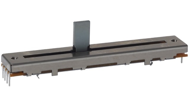
Structurally, variable resistors are divided into resistors with linear movement of the slider (Fig. 1), resistors with circular movement of the slider (Fig. 2) and tuning resistors for adjusting and tuning electronic circuits (Fig. 3). According to parameters, variable resistors are divided according to nominal resistance, power and the dependence of the change in resistance on changes in the position of the slider. For example, the designation SP3-23a 22 kOhm 0.25 W means: Variable resistance, model No. 23, type “A” resistance change characteristic, nominal resistance 22 kOhm, power 0.25 Watt.

Variable resistors are widely used in radio and electronic devices as regulators, tuning elements, and controls. For example, you are probably familiar with radio equipment such as a radio or stereo system. They use variable resistors as volume, tone, and frequency controls.

The figure shows a fragment of a block of tone and volume controls for a music center, and the tone control uses linear slider variable resistors, and the volume control has a rotating slider.

Let's take a look at the variable resistor... What do we know about it? Nothing yet, because we don’t even know the basic parameters of this radio component, which is very common in electronics. So let's learn more about the parameters of variables and trimming resistors.

To begin with, it is worth noting that variable and trimming resistors are passive components of electronic circuits. This means that they consume energy from the electrical circuit during their operation. Passive circuit elements also include capacitors, inductors and transformers.
They don’t have too many parameters, with the exception of precision products that are used in military or space technology:
Nominal resistance. Without a doubt, this is the main parameter. The total resistance can range from tens of ohms to tens of megaohms. Why total resistance? This is the resistance between the outermost fixed terminals of the resistor - it does not change.
Using the adjusting slider, we can change the resistance between any of the extreme terminals and the terminal of the moving contact. The resistance will vary from zero to the full resistance of the resistor (or vice versa - depending on the connection). The nominal resistance of the resistor is indicated on its body using an alphanumeric code (M15M, 15k, etc.)
Dissipated or rated power. In normal electronic equipment Variable resistors are used with a power of: 0.04; 0.25; 0.5; 1.0; 2.0 watts or more.
It is worth understanding that wirewound variable resistors, as a rule, are more powerful than thin-film resistors. Yes, this is not surprising, because a thin conductive film can withstand much less current than a wire. Therefore, the power characteristics can be roughly judged even by appearance"variable" and its construction.
Maximum or limit operating voltage. Everything is clear here. This is the maximum operating voltage of the resistor, which should not be exceeded. For variable resistors, the maximum voltage corresponds to the series: 5, 10, 25, 50, 100, 150, 200, 250, 350, 500, 750, 1000, 1500, 3000, 8000 Volts. Ultimate voltages of some specimens:
SP3-38 (a - d) for a power of 0.125 W - 150 V (for operation in AC and direct current);
SP3-29a- 1000 V (for operation in AC and DC circuits);
SP5-2- from 100 to 300 V (depending on modification and rated resistance).
TCR - temperature coefficient of resistance. A value showing the change in resistance when the ambient temperature changes by 1 0 C. For electronic equipment operating in difficult conditions climatic conditions, this parameter very important.
For example, for trimming resistors SP3-38 the TCR value corresponds to ±1000 * 10 -6 1/ 0 C (with resistance up to 100 kOhm) and ±1500 * 10 -6 1/ 0 C (over 100 kOhm). For precision products, the TCS value lies in the range from 1 * 10 -6 1/ 0 C to 100 * 10 -6 1/ 0 C. It is clear that the smaller the TCR value, the more thermally stable the resistor.
Tolerance or accuracy. This parameter is similar to the tolerance for fixed resistors. Indicated as a percentage. For trimmer and variable resistors for household equipment, the tolerance usually ranges from 10 to 30%.
Working temperature. The temperature at which the resistor properly performs its functions. Usually indicated as a range: -45 ... +55 0 C.
Wear resistance- the number of cycles of movement of the moving system of a variable resistor, during which its parameters remain within normal limits.
For particularly precise and important (precision) variable resistors, wear resistance can reach 10 5 - 10 7 cycles. True, the resistance to shock and vibration of such products is lower. Adjustment resistors are more resistant to mechanical stress, but their wear resistance is less than that of precision resistors, from 5,000 to 100,000 cycles. For tuning ones, this value is noticeably smaller and rarely exceeds 1000 cycles.
Functional characteristics. An important parameter is the dependence of the change in resistance on the angle of rotation of the handle or the position of the moving contact (for slider resistors). This parameter is little talked about, but it is very important when designing sound amplification equipment and other devices. Let's talk about it in more detail.
The fact is that variable resistors are produced with different dependences of the change in resistance on the angle of rotation of the handle. This parameter is called functional characteristic. Usually it is indicated on the case in the form of a code letter.
Let's list some of these characteristics:


Therefore, when selecting a variable resistor for homemade electronic designs, you should also pay attention to the functional characteristics!
In addition to those indicated, there are other parameters for variables and trimming resistors. They mainly describe electromechanical and load quantities. Here are just a few of them:
Resolution;
Resistance imbalance of a multi-element variable resistor;
Moment of static friction;
Sliding (rotating) noise;
As you can see, even such an ordinary part has a whole set of parameters that can affect the quality of work electronic circuit. So don't forget about them.
More details about the parameters of constant and variable resistors are described in the reference book.
In one of the previous articles we discussed the main aspects related to working with, so today we will continue this topic. Everything we discussed earlier concerned, first of all, fixed resistors, the resistance of which is a constant value. But it's not the only one existing look resistors, so in this article we will pay attention to elements that have variable resistance.
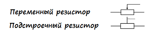
So, what is the difference between a variable resistor and a constant one? Actually, the answer here follows directly from the name of these elements :) The resistance value of a variable resistor, unlike a constant one, can be changed. How? And that’s exactly what we’ll find out! First let's look at the conditional variable resistor circuit:

It can be immediately noted that here, unlike resistors with a constant resistance, there are three terminals, not two. Now let’s figure out why they are needed and how it all works :)
So, the main part of a variable resistor is a resistive layer that has a certain resistance. Points 1 and 3 in the figure are the ends of the resistive layer. Another important part of the resistor is the slider, which can change its position (it can take any intermediate position between points 1 and 3, for example, it can end up at point 2 as in the diagram). Thus, in the end we get the following. The resistance between the left and center terminals of the resistor will be equal to the resistance of section 1-2 of the resistive layer. Similarly, the resistance between the central and right terminals will be numerically equal to the resistance of section 2-3 of the resistive layer. It turns out that by moving the slider we can get any resistance value from zero to . A is nothing more than the total resistance of the resistive layer.
Structurally, variable resistors are rotary, that is, to change the position of the slider you need to turn a special knob (this design is suitable for the resistor shown in our diagram). Also, the resistive layer can be made in the form of a straight line, accordingly, the slider will move straight. Such devices are called sliding or sliding variable resistors. Rotary resistors are very common in audio equipment, where they are used to adjust volume/bass, etc. Here's what they look like:

Variable resistor The slider type looks a little different:
Often when using rotary resistors, switch resistors are used as volume controls. Surely you have come across such a regulator more than once - for example, on radios. If the resistor is in its extreme position (minimum volume/device is turned off), then if you start to rotate it, you will hear a noticeable click, after which the receiver will turn on. And with further rotation the volume will increase. Similarly, when decreasing the volume - when approaching the extreme position, there will be a click again, after which the device will turn off. A click in this case indicates that the receiver's power has been turned on/off. Such a resistor looks like this:

As you can see, there are two additional pins here. They are precisely connected to the power circuit in such a way that when the slider rotates, the power circuit opens and closes.
There is another large class of resistors that have a variable resistance that can be changed mechanically - these are trimming resistors. Let's spend a little time on them too :)
Trimmer resistors.
Just to start, let’s clarify the terminology... Essentially trim resistor is variable, because its resistance can be changed, but let's agree that when discussing trimming resistors, by variable resistors we will mean those that we have already discussed in this article (rotary, slider, etc.). This will simplify the presentation, since we will be contrasting these types of resistors with each other. And, by the way, in the literature, trimming resistors and variables are often understood as different circuit elements, although, strictly speaking, any trim resistor is also variable due to the fact that its resistance can be changed.
So, the difference between trimming resistors and the variables that we have already discussed, first of all, lies in the number of cycles of moving the slider. If for variables this number can be 50,000 or even 100,000 (that is, the volume knob can be turned almost as much as you like 😉), then for trimming resistors this value is much less. Therefore, trimming resistors are most often used directly on the board, where their resistance changes only once, when setting up the device, and during operation the resistance value does not change. Externally, the tuning resistor looks completely different from the mentioned variables:

The designation of variable resistors is slightly different from the designation of constant ones:
Actually, we have discussed all the main points regarding variables and trimming resistors, but there is one more very important point that cannot be ignored.
Often in the literature or in various articles you can come across the terms potentiometer and rheostat. In some sources this is what variable resistors are called, in others these terms may have some other meaning. In fact, there is only one correct interpretation of the terms potentiometer and rheostat. If all the terms that we have already mentioned in this article related, first of all, to the design of variable resistors, then a potentiometer and a rheostat are different circuits for connecting (!!!) variable resistors. That is, for example, a rotary variable resistor can act both as a potentiometer and as a rheostat - it all depends on the connection circuit. Let's start with the rheostat.
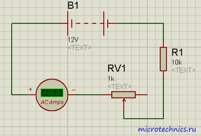
(a variable resistor connected in a rheostat circuit) is mainly used to regulate the current. If we connect an ammeter in series with the rheostat, then when we move the slider we will see a changing current value. The resistor in this circuit plays the role of a load, the current through which we are going to regulate with a variable resistor. Let the maximum resistance of the rheostat be equal to , then, according to Ohm’s law, the maximum current through the load will be equal to:
Here we took into account that the current will be maximum at a minimum value of resistance in the circuit, that is, when the slider is in the extreme left position. The minimum current will be equal to:

So it turns out that the rheostat acts as a regulator of the current flowing through the load.
There is one problem with this circuit - if contact is lost between the slider and the resistive layer, the circuit will be open and current will stop flowing through it. You can solve this problem as follows:

The difference from the previous diagram is that points 1 and 2 are additionally connected. What does this give in normal operation? Nothing, no changes 🙂 Since there is non-zero resistance between the resistor slider and point 1, all the current will flow directly to the slider, as in the absence of contact between points 1 and 2. What happens if contact between the slider and the resistive layer is lost? And this situation is absolutely identical to the absence of a direct connection of the slider to point 2. Then the current will flow through the rheostat (from point 1 to point 3), and its value will be equal to:
That is, if contact is lost in this circuit, there will only be a decrease in the current strength, and not a complete break in the circuit as in the previous case.
WITH rheostat We figured it out, let's look at a variable resistor connected according to the potentiometer circuit.

Don't miss the article about measuring instruments in electrical circuits –
Unlike a rheostat, it is used to regulate voltage. It is for this reason that in our diagram you see two voltmeters :) The current flowing through the potentiometer, from point 3 to point 1, remains unchanged when moving the slider, but the resistance value between points 2-3 and 2-1 changes. And since voltage is directly proportional to current and resistance, it will change. When moving the slider down, the resistance of 2-1 will decrease, and accordingly, the readings of voltmeter 2 will also decrease. With this movement of the slider (down), the resistance of section 2-3 will increase, and with it the voltage on voltmeter 1. In this case, the total readings of the voltmeters will be will be equal to the voltage of the power source, that is, 12 V. In the uppermost position on voltmeter 1 there will be 0 V, and on voltmeter 2 - 12 V. In the figure, the slider is located in the middle position, and the readings of the voltmeters, which is absolutely logical, are equal :)
This is where we finish looking at variable resistors, in the next article we will talk about possible connections between resistors, thank you for your attention, I will be glad to see you on our website! 🙂
Last time, to connect the LED to a 6.4 V DC source (4 AA batteries), we used a resistor with a resistance of about 200 Ohms. This, in principle, ensured normal operation of the LED and prevented it from burning out. But what if we want to adjust the brightness of the LED?
For this the most simple option will use a potentiometer (or trimming resistor). In most cases, it consists of a cylinder with a resistance adjustment knob and three contacts. Let's figure out how it works.
It should be remembered that it is correct to adjust the brightness of the LED by PWM modulation, and not by changing the voltage, since for each diode there is an optimal operating voltage. But to clearly demonstrate the use of a potentiometer, such use of it (the potentiometer) for educational purposes is acceptable.
By releasing the four clamps and removing the bottom cover, we will see that the two outer contacts are connected to the graphite track. The middle contact is connected to the ring contact inside. And the adjustment knob simply moves the jumper connecting the graphite track and the ring contact. When you rotate the knob, the arc length of the graphite track changes, which ultimately determines the resistance of the resistor.
 It should be noted that when measuring the resistance between the two extreme contacts, the multimeter reading will correspond to the nominal resistance of the potentiometer, since in this case the measured resistance corresponds to the resistance of the entire graphite track (in our case 2 kOhm). And the sum of resistances R1 and R2 will always be approximately equal to the nominal value, regardless of the angle of rotation of the adjustment knob.
So, by connecting a potentiometer in series to the LED, as shown in the diagram, changing its resistance, you can change the brightness of the LED. Essentially, when we change the resistance of the potentiometer, we change the current passing through the LED, which leads to a change in its brightness.

 However, it should be remembered that for each LED there is a maximum permissible current, if exceeded, it simply burns out. Therefore, to prevent the diode from burning out when the potentiometer knob is turned too far, you can connect another resistor in series with a resistance of about 200 Ohms (this resistance depends on the type of LED used) as shown in the diagram below.

For reference: LEDs need to be connected with the long “leg” to +, and the short one to -. Otherwise, the LED simply will not light up at low voltages (it will not pass current), and at a certain voltage, called the breakdown voltage (in our case it is 5 V), the diode will fail.
A large number of people turn to radio stores to do something with their own hands. The main task of those who like to collect radios and circuits is to create useful items that will benefit not only themselves, but also those around them. A variable resistor helps to carry out repairs or create a device that operates from an electrical network.
Basic properties of variable resistors
When a person has a clear idea of the conventional elements of graphic display on diagrams, then he has the problem of transferring the drawing into reality. You need to find or purchase individual components of a ready-made circuit. Today there are a large number of stores that sell the necessary parts. You can also find elements in old broken radio equipment.
A variable resistor must be present in any circuit. It is found in any electronic devices. This design is a cylinder that includes diametrically opposed terminals. The resistor creates a limit on the flow of current in the circuit. If necessary, it will perform resistance, which can be measured in ohms. A variable resistor is indicated on the diagram in the form of a rectangle along with two dashes. They are located on opposite sides inside the rectangle. Thus, a person denotes power on his diagram.
The equipment, which is found in almost every home, includes resistors with a certain value. They are located along the E24 row and conventionally indicate the range from one to ten.
Types of resistors
Today there are a large number of resistors that are found in modern household electrical appliances. The following types can be distinguished:
- Heat-resistant varnished metal resistor. It can be found in lamp devices that have a power of at least 0.5 watts. In Soviet equipment you can find resistors that were produced in the early 80s. They have different powers, which directly depend on the size and dimensions of the radio equipment. When there is no power symbol on the diagrams, then it is allowed to use a variable resistor of 0.125 watts.
- Waterproof resistors. In most cases, they are found in lamp-based electrical appliances that were manufactured in 1960. These elements are sure to be found in black-and-white TV and radios. Their markings are very similar to the designation of metal resistors. Depending on the rated power, they can have different sizes and dimensions.
Today, generally accepted markings of resistors are widely used, which are divided into different colors. This way you can quickly and easily determine the value without soldering the circuit. Thanks to color coding, you can significantly speed up the search for the required resistor. Nowadays, a large number of foreign and domestic companies are engaged in the production of such elements for microcircuits.

Main characteristics and parameters of a variable resistor
Several main parameters can be distinguished:

Specific characteristics are used during the design of the presented devices. These parameters apply to devices that operate at high frequencies:
A wirewound variable resistor is considered the main and main element in any electronic equipment. It is applied as a discrete component or component to an integrated circuit. It is classified according to basic parameters, such as method of protection, installation, nature of resistance changes or production technology.
Classification by general use:
- General purpose.
- Special purpose. They are high-resistance, high-voltage, high-frequency or precision.
Depending on the nature of the change in resistance, the following resistors can be distinguished:
- Permanent.
- Variables, adjustable.
- Adjusted variables.
If we take into account the method of protecting resistors, we can distinguish the following designs:

Connecting a variable resistor
A large number of people do not know how to connect a variable resistor. These elements often have two connection schemes. This work can be done by a person who has at least a little knowledge of electronics and has dealt with soldering microcircuits.

Manufacturing technology of variable resistors
There is a classification that depends on the resistor manufacturing technology. During the production process, different steps and patterns are used. Today we can distinguish the following designs:

Features of 10 kOhm variable resistors
Today in radio markets you can find a large number of elements for drawing up a diagram. The most popular is a 10 kOhm variable resistor. It can be variable, wire or adjustable. Main it distinctive feature- single single-revolution. This type of resistor is designed to work in an electrical circuit where there is direct or alternating current.
The power rating is 50 volts and the resistance is 15 kOhm. These elements were produced in the mid-eighties, so today they can be found not only in specialized stores, but also in old radio circuits. The 10 kOhm variable resistor has several functional and possible analogues.

Variable resistor noise
Even new and reliable resistors at high temperatures, which are well above absolute zero, can become the main source of noise. A dual variable resistor is used in an electrical circuit in a microcircuit. The appearance of noise became known from the fundamental fluctuation-dissipation theorem. It is commonly known as the Nyquist theorem.
If the circuit contains a variable resistor SP with high resistance values, then a person will observe an effective noise voltage. It will be directly proportional to the roots of the temperature regime.
Potentiometer is a device that most of us associate with the volume knob protruding from the radio. Today, in the era digital circuits The potentiometer is not used very often.
However, this device has a special charm and it cannot be replaced where smooth “analog” adjustment is needed. For example, if you play on a game console with a gamepad. The gamepad has analog knobs, which often consist of 2 potentiometers. One controls the horizontal axis, and the other controls the vertical axis. Thanks to these potentiometers, the game becomes more precise than with a regular digital joystick.
The potentiometer is a variable resistor. A resistor is a radio element that makes it difficult for current to flow through it. It is used where it is necessary to reduce voltage or current.
An adjustable resistor or potentiometer serves the same purpose, except that it does not have a fixed resistance, but changes as required by the user. This is very convenient because everyone prefers different volume, brightness and other characteristics of the device that can be adjusted.

Today we can say that the potentiometer does not regulate the functional characteristics of the device (this is done by the circuit itself with a digital display and buttons), but it serves to change its parameters, such as control in a game, deflection of the ailerons of a remotely controlled aircraft, rotation of a CCTV camera, etc.
How does a potentiometer work?
A traditional potentiometer has a shaft on which a knob is placed to change the resistance, and 3 terminals.
The two outer terminals are connected by electrically conductive material with a constant resistance. In fact, it is a constant resistor. The central terminal of the potentiometer is connected to a movable contact that moves along an electrically conductive material. As a result of changing the position of the moving contact, the resistance between the central terminal and the outer terminals of the potentiometer also changes.
Thus, the potentiometer can change its resistance between the central contact and any of the outer contacts from 0 ohms to the maximum value indicated on the body.
Schematically, the potentiometer can be represented as two constant resistors:

In the voltage divider, the extreme terminals of the resistors are connected between the Vcc power supply and the ground GND. And the middle pin from GND creates a new lower voltage.
Uout = Uin*R2/(R1+R2)
If we have a resistor with a maximum resistance of 10 kOhm and move its handle to the middle position, then we will get 2 resistors with a value of 5 kOhm. By applying a voltage of 5 volts to the input, at the output of the divider we get the voltage:
Uout = Uin * R2/(R1+R2) = 5*5000/(5000+5000) = 5*5/10 = 5*1/2 = 2.5V
The output voltage turned out to be equal to half the input voltage.
What happens if we turn the knob so that the central pin is connected to the Vcc pin?
Uout = Uin*R2/(R1+R2) = 5*10000/(0+10000) = 5*10000/10000 = 5*1 = 5V
Since the resistance of resistor R1 decreased to 0 Ohm, and the resistance of R2 increased to 10 kOhm, we received the maximum output voltage at the output.
What happens if we turn the handle all the way in the opposite direction?
Uout = Uin*R2/(R1+R2) = 5*0/(10000 0) = 5*0 = 0V
In this case, R1 will have a maximum resistance of 10 kOhm, and R2 will drop to 0. In fact, there will be no voltage at the output.


