With the help of electronic relays you can save money quite well, for example, let's take light in the corridor, storage room or entrance. By pressing the button, we turn on the light and after a certain time it automatically turns off. This time should be enough to search for the item in the hallway, closet, or get into the apartment. In addition, the lighting does not turn on unnecessarily if you forget to turn it off. This device is not only useful, but also very convenient. In this article we will tell you how to make a time relay with your own hands, providing all the necessary diagrams and instructions.
The simplest option
An example of a constructor for a homemade shutdown delay timer:
If desired, it is possible to independently assemble a time relay according to the following scheme:
The timing element is C1; in the standard configuration of the KIT set it has the following characteristics: 1000 µF/16 V, the delay time in this case is approximately 10 minutes. Time adjustment is carried out by variable R1. The board's power supply is 12 Volts. The load is controlled through relay contacts. You don’t have to make the board, but assemble it on a breadboard or mounted it.

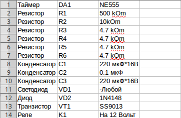
In order to make a time relay, we need the following parts:

A correctly assembled device does not require configuration and is ready for use. This homemade time delay relay was described in the magazine “Radiodelo” 2005.07.
Homemade product based on NE 555 timer
Another electronic timer circuit for DIY assembly is also easy and easy to repeat. The heart of this circuit is the NE 555 integrated timer chip. This device is designed to both turn off and turn on devices; below is a diagram of the device:

NE555 is a specialized chip used in the construction of all kinds of electronic devices, timers, signal generators, etc. It is common enough that it can be found in any radio store. This microcircuit controls the load through an electromechanical relay, which can be used to both turn on and off the payload.
The timer is controlled by two buttons: “start” and “stop”. To start counting time, you must press the “start” button. The device is turned off and returned to its original state using the “stop” button. The node that sets the time interval is a chain of variable resistor R1 and electrolytic capacitor C1. The value of the turn-on delay depends on their rating.
With the given values of elements R1 and C1, the time range can be from 2 seconds to 3 minutes. An LED connected in parallel to the relay coil is used as an indicator of the operating status of the structure. As in the previous circuit, its operation requires an additional 12 Volt external power source.
In order for the relay to turn on itself immediately when power is applied to the board, it is necessary to slightly change the circuit: connect pin 4 of the microcircuit to the positive wire, disconnect pin 7, and connect pins 2 and 6 together. You can learn more clearly about this scheme from the video, which describes in detail the process of assembling and working with the device:
Single transistor relay
The simplest option is to use a time relay circuit with just one transistor, KT 973 A, its imported analogue BD 876. This solution is also based on charging the capacitor to the supply voltage, through a potentiometer (variable resistor). The highlight of the circuit is the forced switching and discharge of the capacitance through resistor R2 and the return of the original initial position with toggle switch S1.

When power is applied to the device, capacitance C1 begins to charge through resistor R1 and through R3, thereby opening transistor VT1. When the capacity is charged to the VT1 shutdown state, the relay is de-energized, thereby turning off or turning on the load, depending on the purpose of the circuit and the type of relay used.
The elements you select may have a slight variation in ratings; this will not affect the performance of the circuit. The delay may vary slightly and depend on the ambient temperature, as well as the magnitude of the mains voltage. The photo below provides an example of a finished homemade product:

Now you know how to make a time relay with your own hands. We hope the instructions provided were useful to you and you were able to assemble this homemade product at home!
Schematic diagrams of time delay relays, automatic switches and 220V load switches with a given time interval. The circuits are easy to assemble and are based on the LM555 chip.
Time relay for automatic load shedding
Sometimes it is necessary to turn off the receiver or backlight after a certain period of time. This problem can be solved by the circuit shown in Fig. 1.
Rice. 1. Timer circuit for automatic load shutdown.
With the ratings of the timing elements indicated in the diagram, the shutdown delay will be about 40 minutes (for micropower timers, this time can be significantly increased, since they allow R2 to be set with a higher rating).
In standby mode, the device does not consume power, since transistors VT1 and VT2 are locked. Switching on is done by button SB1 - when pressed, transistor VT2 opens and supplies power to the microcircuit. At the output of timer 3, a voltage appears, which opens the transistor switch VT1 and supplies voltage to the load, for example, to the BL1 lamp.
The button is blocked, and the circuit will remain in this state while capacitor C2 is charging, after which it will turn off the load. Resistor R3 limits the discharge current of the timing capacitor, which increases the reliability of the device. To obtain large delay intervals, capacitor C2 must be used with a low leakage current, for example tantalum from the K52-18 series.
Timer with extended time interval
A diagram of a device for a similar purpose is shown in Fig. 2. It allows you to discretely change the load shutdown delay time from 5 to 30 minutes (in steps of 5 minutes) using switch SA1. Thanks to the use of a micro-power timer with a high input resistance, it is possible to use timing resistors of significantly larger values (from 8.2 to 49.2 MOhm), which makes it possible to increase the time interval: T = 1.1 * C2 * (R1 + .. . + Rn).

Rice. 2. Timer circuit with an increased time interval to disconnect the load.
Triac time relay circuits
Schemes that allow you to directly (without a relay) control the disconnection of the network load are shown in Fig. 3 and 4. They use a triac as a switch. Compared to the original, in the options presented here, some ratings have been changed to allow devices to operate on 220 V mains voltage.
In the diagram in Fig. 3, the load is turned on immediately when contacts SA1 are closed, and turned off with a delay determined by the ratings R2-C2 (for those indicated in the diagram it is 11 seconds). Circuit R1-C1 ensures that the one-shot device starts when turned on.

Rice. 3. Transformerless network load control circuit.

Rice. 4. Scheme option for automatically disconnecting the network load.
In the second scheme (Fig. 4), the load will be turned on when initially connecting to the network or when pressing the SB1 button. To power the microcircuit, a reactance is used, which is capacitor C1 (it does not heat up, which is better compared to a voltage-damping active resistance, as was done in the previous circuit).
Zener diode VD1 provides a stable supply voltage to the microcircuit, and diode VD3 allows you to reduce the readiness time of the circuit for frequent pressing of the button. The turn-off delay time can be adjusted by resistor R3 from 0 to 8.5 minutes. The timing capacitor SZ must have a small leakage.
Literature: For radio amateurs: useful diagrams, Book 5. Shelestov I.P.
Today, there are many devices designed to make the life of a modern person easier. Thus, time relays have also moved from the industrial sphere to the household sphere, making it possible to automate the operation of modern electrical appliances and systems. What types of time relays are offered on the modern market, how to choose a time regulator and assemble the device with your own hands - read below.
What is a time delay relay
Time delay relays are special devices, the main purpose of which is to ensure sequential operation of circuit elements for a certain time after turning the power on or off. The delays created by the relay can be either minute or hour long, daily or weekly. At the same time, with the help of one signal, the relay is able to simultaneously control the operation of several circuits.
According to the principle of operation, time delay relays are divided into devices:
- With electromagnetic retardation;
- With pneumatic deceleration mechanism;
- With clock or anchor mechanism;
- Motor type.
Separately, electronic time relays are distinguished. The time delay in such devices is implemented using analog and digital technical solutions. Often these solutions are represented by digital timers.

Electronic relays have become widespread due to the widest range of time delay adjustments.
Thus, an electronic relay is capable of monitoring the operation of circuit elements with a time delay from a fraction of a second to several thousand hours. In addition, the advantages of electronic relays include their small size, economical energy consumption and versatility. There are also time relays that operate on microprocessors. Such models are considered the most effective.
Classification of time delay relays
For convenience, time relays are classified by type of design. This classification makes it possible to divide devices into relays for industrial use and household controllers.
So, all temporary delay relays are divided into:
- Monoblock;
- Built-in;
- Modular.
Monoblock and modular devices are the easiest to install. Monobloc relays are self-contained devices for external installation. Such devices are equipped with built-in batteries and have terminals for connecting the load. Modular relays are a type of monoblock relays, and are used for installation in electrical panels.

The most common in industrial and commercial applications are built-in relays.
They are actively used in modern household electrical installations (for example, washing machines) and smart home systems. In addition, such devices are used in greenhouse automation.
Scope of application of time relay with switch-off delay
The scope of application of temporary relays is extremely wide and depends on the type of device. Thus, all time relays are divided into devices with a delay on switching on after power is applied and devices with a time delay on switching off after disconnecting the load. The most common in the domestic sphere and public utilities are relays with a time delay to turn off.
Most often, devices that create a shutdown delay are used for:
- Automation of street and indoor lighting;
- Control over irrigation systems;
- Automation of ventilation systems;
- Control over the operation of household pumps, gas boilers, electric water heaters.
Thus, time relays allow you to use various electrical equipment only according to its actual need, eliminating the possibility of its inappropriate use. This not only saves energy consumption, but also extends the life of electrical appliances.
Relays with a turn-on time delay are used to control the operation of industrial and household automation.
For example, the devices can be used to automatically restore the operation of household appliances, lighting, ventilation, and heating systems after the power supply is restored. With proper connection and good configuration, relays with a turn-on delay can activate the “warm floor” system when you arrive, turn on water heaters and household appliances (for example, a coffee machine) after you wake up.
The main criterion for choosing a time relay for single-phase networks (220 V) is the delay range. This parameter is determined by the purpose of the shutdown device. So, for example, for a relay connected to a fan in the bathroom, a shutdown delay in the range from 1 second to 1 hour will be sufficient.
Time delay relays usually have a smaller range.
This is due to the scope of their use. Often, after the power supply is restored, industrial, household and household automation must be switched on immediately. Thus, the delay for turning on household electrical equipment should be no more than 2 minutes.

In addition, when choosing a time relay, you must consider:
- Type of switched current. Relays can switch both alternating and direct current. For switching alternating current, you should choose an AC type relay, for switching direct current, a DC type. There are also universal devices labeled AC/DC.
- Maximum switching current. Relays capable of switching loads in the range from 10 to 16 A are suitable for household use.
- Device protection level. Relays with index IP20 are suitable for indoor installation. For outdoor installation, this figure must be doubled, or the relay must be installed in a protective housing.
- Relay connection options. Some models of temporary relays can be simultaneously connected to two elements that control the load (for example, to two switches). So the operation of the relay can be controlled from two points located at different ends of the room.
Do not forget about the overall dimensions and method of installation of the device. This will allow you to quickly fit the device into the project. Thus, electronic installations have the smallest dimensions. Additionally, the temporary relay may or may not require DIN rail mounting.
12 volt relay switch-on delay circuit
You can assemble a simple relay with your own hands. The easiest electronic time relay circuit to implement is assembled on the basis of the ne555 integrated timer. The relay is controlled by pressing external keys. 12V will be enough to operate the device. The relay can be powered via a power cable to the mains. A 12-volt battery can also temporarily support the operation of the relay.
The circuit of a simple time relay based on the NE 555 timer also has the following features:
- The unit that sets the time interval is a circuit of an AC resistor and an electrolytic capacitor. The delay interval for switching on the time relay depends on their rating
- With a resistor value of 500 kOhm and a capacitor of 220 μF, the delay range can be from 2 seconds to 3 minutes.
- An indicator of the relay's performance can be an LED connected in parallel to the coil.
This device can be used to both turn off and turn on electrical equipment with a time delay. To start the time countdown, you must press the “start” button, which starts the timer. The “stop” button is responsible for turning off the power and returning the relay-controlled device to its original state.
Greetings! I present to you several time relay and load shutdown delay circuits. The load can be either a light bulb or a TV. Let your imagination run wild.
This circuit is needed to turn off something after a certain time interval.
Fig.1. Timer circuit for automatic load shedding.
With the ratings of the timing elements indicated in the diagram, the shutdown delay will be about 40 minutes (for micropower timers, this time can be significantly increased, since they allow R2 to be set with a higher rating).
In standby mode, the device does not consume power, since transistors VT1 and VT2 are locked. Switching on is done by button SB1 - when pressed, transistor VT2 opens and supplies power to the microcircuit. At the output of timer 3, a voltage appears, which opens the transistor switch VT1 and supplies voltage to the load, for example, to the BL1 lamp. The button is blocked, and the circuit will remain in this state while capacitor C2 is charging, after which it will turn off the load. Resistor R3 limits the discharge current of the timing capacitor, which increases the reliability of the device. To obtain large delay intervals, capacitor C2 must be used with a low leakage current, for example tantalum from the K52-18 series.
The following diagram is for turning off the load after 5-30 minutes in 5 minute increments by pressing the SA1 button.
Thanks to the use of a micro-power timer with a high input resistance, it is possible to use timing resistors of significantly larger values (from 8.2 to 49.2 MOhm), which makes it possible to increase the time interval: T = 1.1 * C2 * (R1 + .. . + Rn).

Fig.2. Timer circuit with extended time interval for load shedding
Circuits that allow you to directly (without a relay) control the disconnection of the network load are shown in Figs. 3 and 4. In them, a triac is used as a switch. Compared to the original, in the options presented here, some ratings have been changed to allow devices to operate on 220 V mains voltage.
In the circuit in Fig. 3, the load is turned on immediately when contacts SA1 are closed, and turned off with a delay determined by the ratings R2-C2 (for those indicated in the diagram it is 11 s). Circuit R1-C1 ensures that the one-shot device starts when turned on.

Fig.3. Transformerless network load control circuit

Fig.4. Circuit for automatic shutdown of network load
In the second scheme (Fig. 4), the load will be turned on when initially connecting to the network or when pressing the SB1 button. To power the microcircuit, a reactance is used, which is capacitor C1 (it does not heat up, which is better compared to a voltage-damping active resistance, as was done in the previous circuit). Zener diode VD1 provides a stable supply voltage to the microcircuit, and diode VD3 allows you to reduce the readiness time of the circuit for frequent pressing of the button. The turn-off delay time can be adjusted by resistor R3 from 0 to 8.5 minutes. The timing capacitor SZ must have a small leakage.
Literature: For radio amateurs: useful diagrams, Book 5. Shelestov I.P.
Hello friends!
Today we will take a detailed look at the circuit and design of a fairly useful device - a time relay with a load switch-off delay. Of course, the device can be used to both switch on a load and switch between two different loads. The operating voltage of the load can be up to 220V, the maximum switching current is up to 5 A. Using simple calculations, we find that the load power can be up to 1100 W.
Device diagram and principle of its operation
First of all, let's study the time delay relay circuit. An important point: I am not the developer of the scheme and do not claim copyright.
The presented scheme works as follows. When you press the clock button SW1, capacitor C1 is charged, transistor VT1 opens (transistor VT2 and transistor VT3 are in the closed state). Since the relay contacts (X3 and X4) are open, the load is disconnected. During the discharge of capacitor C1, transistor VT1 closes. At the same time, transistors VT2 and VT3 open, and current begins to flow through the relay coil, which leads to the closure of the relay contacts (X3 and X4) and the load being turned on.
You can guess that the main timing element is capacitor C1. The maximum on/off delay time directly depends on it. Also, the relay response time depends on the resistance of the variable resistor R1. Accordingly, to change the delay time, it is enough to change the values of resistor R1 and capacitor C1.
The circuit is powered by a 12 V DC source. Current consumption does not exceed 100 mA.
As for the details. All transistors used in the circuit are of the same type - BC547. These transistors can be replaced with transistors with similar parameters. For example, instead of BC547, you can quite successfully use transistors of the KT3102 series with any letter indices.
Electromechanical relay – BS115C with operating voltage 9V. In principle, the relay can be any small-sized one with an operating voltage from 9 to 12V, for example, it can be a JQC-3F-1C-9VDC relay.
Time relay circuit board
The device is assembled on a printed circuit board made of foil fiberglass, measuring 41x35 mm. For ease of installation, I recommend putting a “diagram” of the arrangement of elements on the board. Drawing the arrangement of elements can be done using the same laser-iron method.
Printed circuit board drawing and arrangement of elements
This is how my printed circuit board turned out:
Switch-off delay relay design
The device can be assembled in absolutely any housing of suitable dimensions. Do not forget that in addition to the relay itself, the power supply must also fit in the case. In my case, a plastic case was used to assemble the power supply. I think that a similar case can be purchased without any problems in almost any radio store.
As you can see, both the board with the relay and the power supply fit into such a case just fine. By the way, you can use a cell phone charger as a power supply. In order to increase the output voltage of such charging, it is enough to replace the zener diode in it with a higher voltage. You can find information on how to do this correctly on YouTube.


